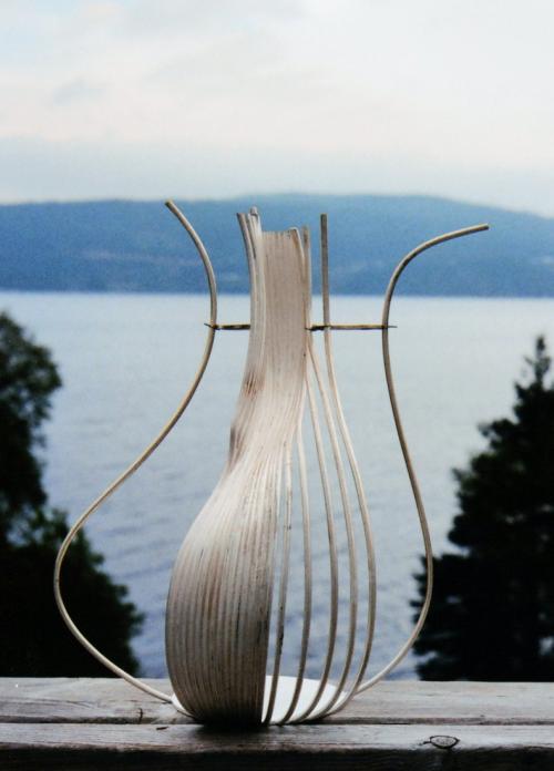
The beginning. A styrofoam model was made as a guide to the form. The first 2 wires are soldered to the base (the wires are 1/8" in diameter). A template is temporarily attached at the narrowest area of the neck.
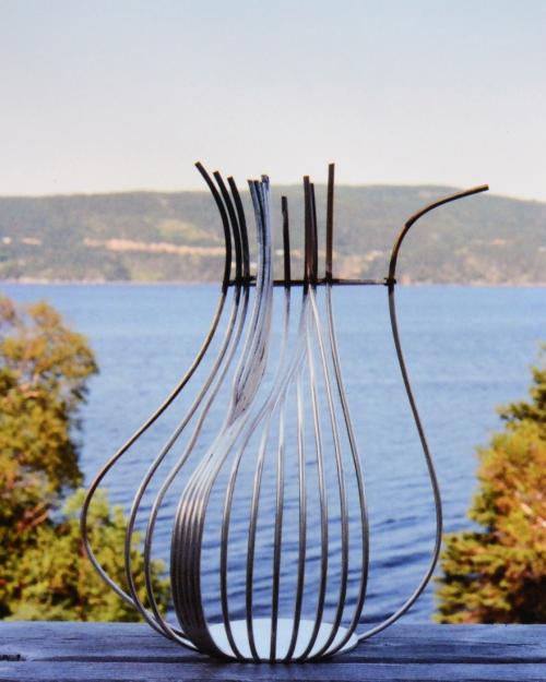
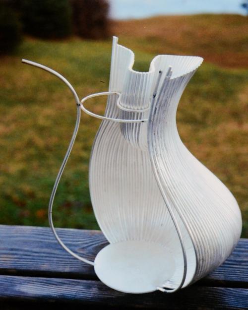
This shows the extent to which a rib-cage-like framework was built before beginning to fill in a solid surface. Medium silver solder was used throughout.
The area of the handle was constructed first because it was the most complex shape and needed to be heated from both sides to avoid over-heating.
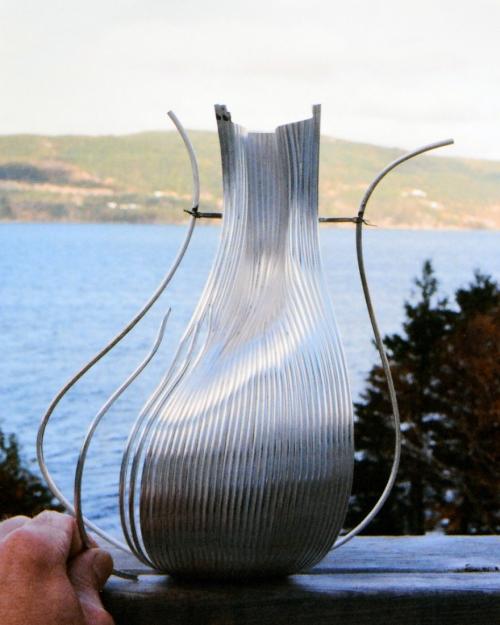
This photograph clearly shows how the process went once the surface was solid. I am holding a wire that has been precisely bent to the needed contour, tapered at both ends, and slightly grooved along the tapered areas. In that way, each wire literally locks itself in place to be soldered.
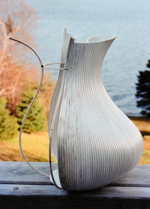
The handle area is fully constructed, and the surface has now reached one of the two original wires. Each soldering usually involves some cleaning up of excess solder on the surface.
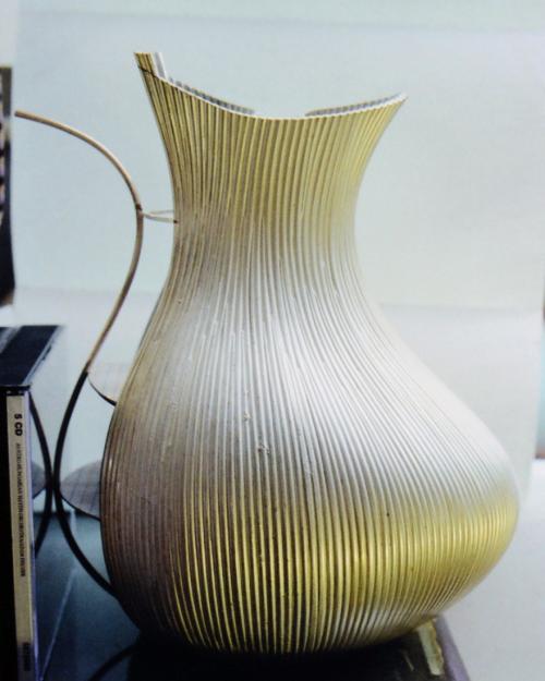
Gradually working around the form, usually at a rate of two or three wires per day. The temporary template is still being used in the narrowest area of the neck.
This photo (and the previous photo) shows how a single wire is soldered at the bottom and near the top, then another wire will divide that gap and be soldered top and bottom, then two more sliver-like wires will be soldered in to fill the two remaining spaces.
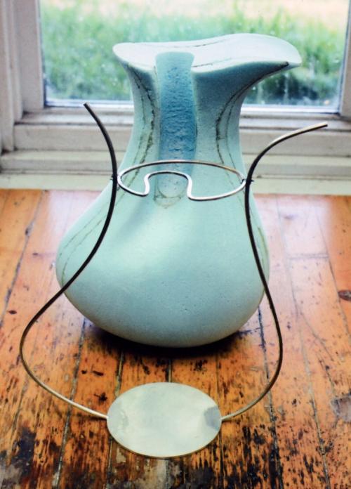
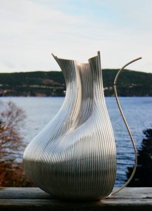
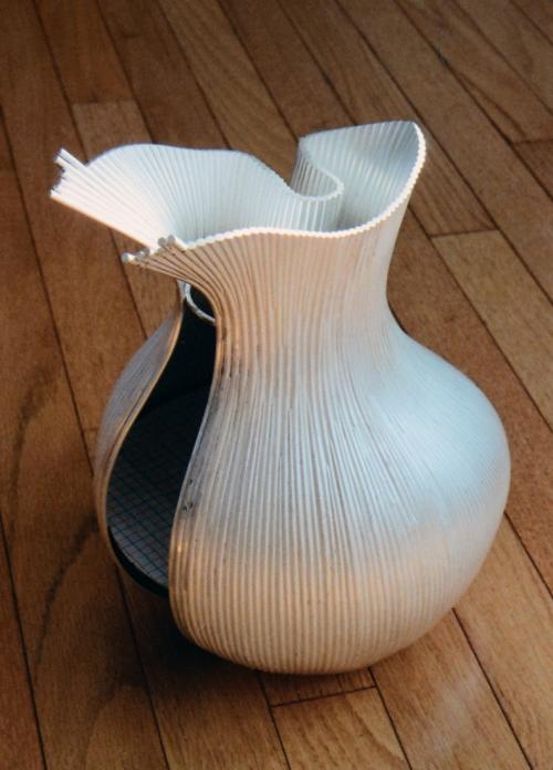
Both sides of the pitcher are now constructed the same distance around. Two cardboard templates (barely visible in this photo) were used throughout the process to maintain symmetry.
Gradually building toward the spout and the front. Each soldering on one side is mirrored by the doing the same thing on the other side.
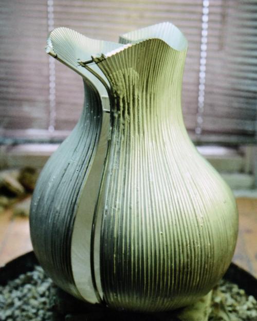
The pitcher is shown ready to be soldered. The wire to be attached is tied with binding wire at the top with a temporary spacer in place. Flux can be seen dried in the area of the join. Under heat, the flux becomes glass-like which keeps the metal clean and helps the solder flow.
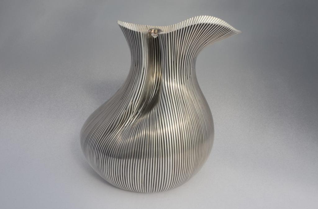
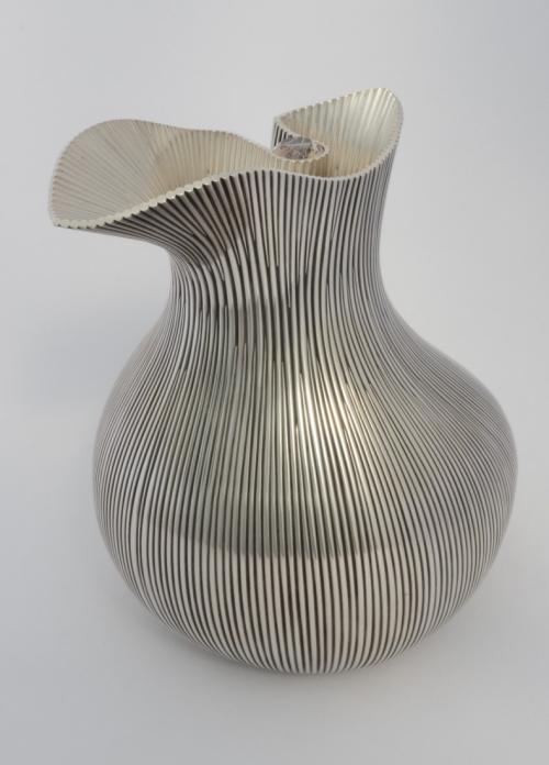
The finished pitcher. The surfaces have been polished and the grooves on the outer surface have been oxidized. A rutillated quartz, facetted by Edgar Hasselfeldt, is set in the curve above the handle area.